Your Dual Battery System Layout
Note: This article contains an affiliate link to My Generator. If you click through and make a purchase, we earn a small commission at no extra cost to you.
Last time, we figured out what parts we need for our dual battery system. Go here to find out more.
Doing The Groundwork
So you’ve worked out what parts you need for your dual battery system. Now you have a couple of decisions to make.
Where is it going to be mounted?
You’ve probably already figured this out – preferably somewhere protected from the elements and out of the way. We had the luxury of space in our truck, so were able to install it inside a storage box.
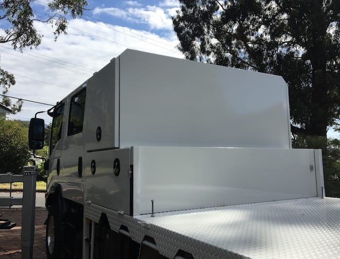
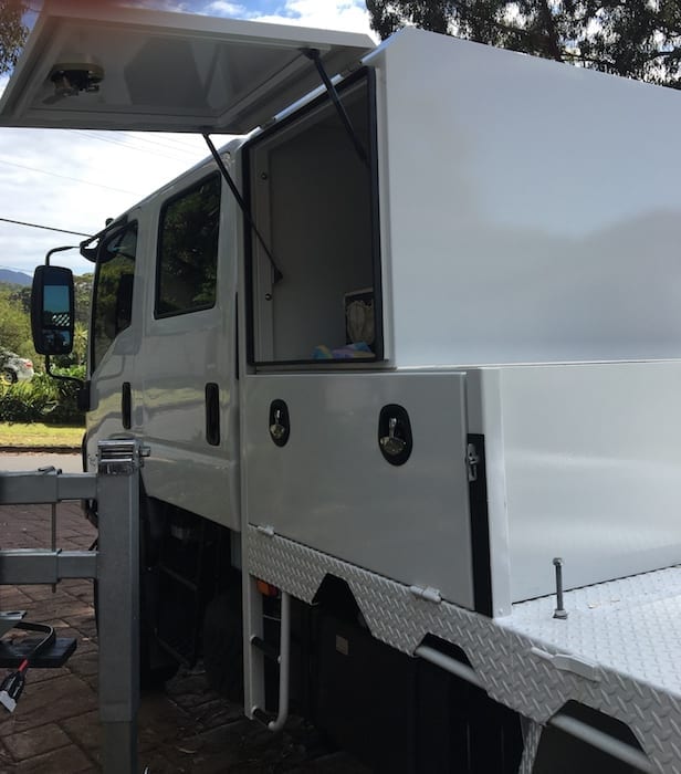
How much space is it going to take up?
This is a bit tricky. Large diameter cables eat up heaps of space. They need plenty of room to run in and out of components without over-bending the cables.
This means you’ll invariably need more space than you first thought. Just try not to cram everything in. Easier said than done when space is limited!
Laying It All Out
I’ll explain how I came up with my dual battery system layout and you can take away ideas as you need them.
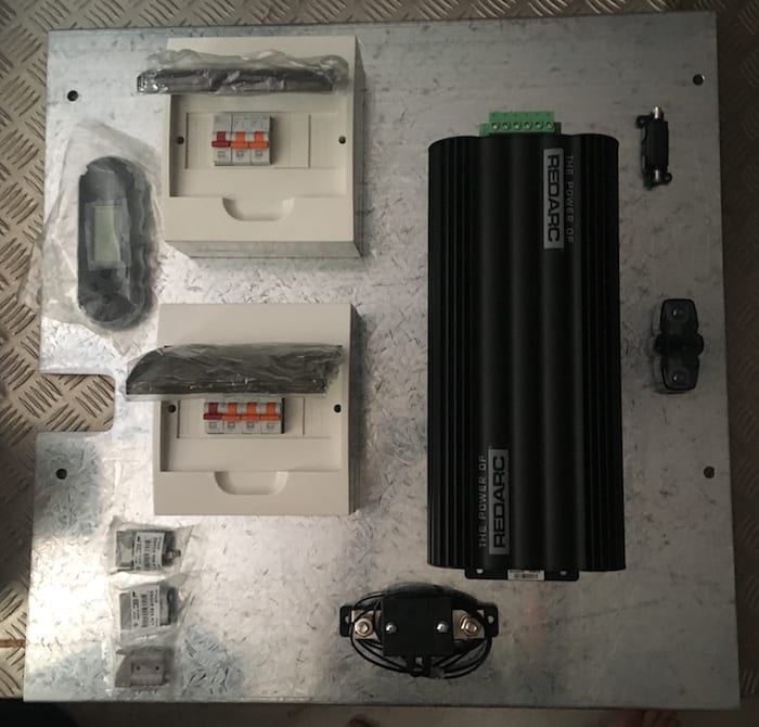
I wanted a really solid backplate because this system is going to be pounded over some rough roads. So the backplate is 2mm thick galvanised mild steel. The top and bottom edges are folded to strengthen the plate. All components will be mounted to the backplate then the entire assembly will be bolted to an inside wall of a storage box.
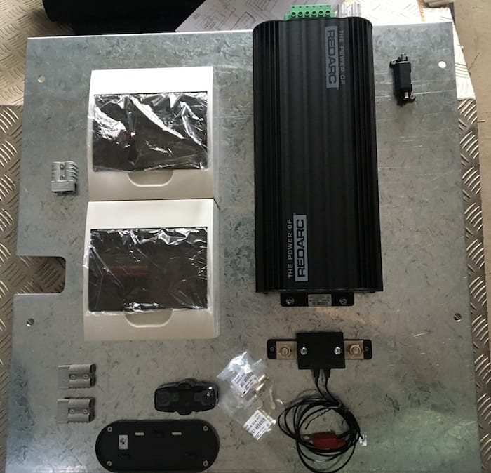
Before you drill any holes, get all of the parts that are going onto the backplate. Then start shuffling them around until you have a layout that makes sense. As you do this, think about where all the cables are running to and from.
Grab A Cuppa
Once you have a layout you’re happy with, leave it for an hour or two. Then come back and have another look. Think about where it will be mounted:
- Will you be able to access fuses and any switches?
- Will you be able to see the digital readouts?
- Some components may need space to dissipate heat. Do they have enough space around them?
- Can you access terminals easily? You want fault-finding to be easy, especially late at night in the middle of nowhere.
- Where do the cables run? Are your parts laid out in a logical flow or will it become a messy spaghetti of cables?
- Will the cables rub on any sharp edges – either on or surrounding the backplate?
For example, have a look at the layout below. This is what I came up with, after a fair bit of thought. But if you look further down, the final layout is quite different. After leaving it alone for a few hours, I moved everything around to get a much better layout.
Start Drilling!
Once you’ve finalised the layout, start drilling. I had about 25mm of air space behind the backplate. So I tried to run most of the cables behind the backplate. This makes for a neater installation.
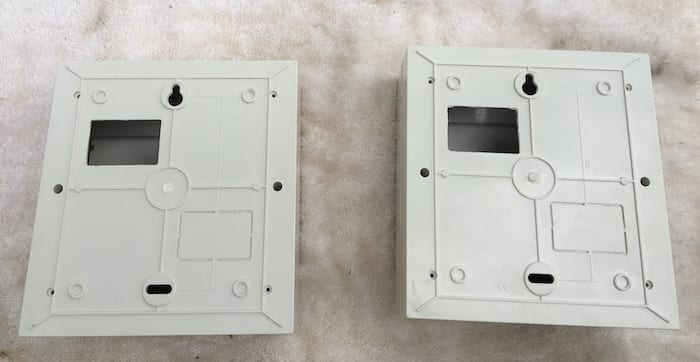
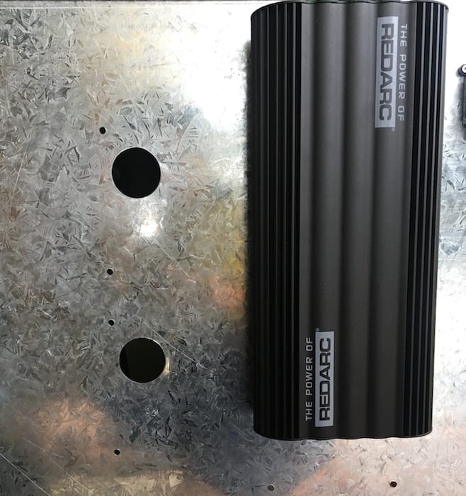
Just a tip on the larger holes. See if you can beg, borrow or steal a hydraulic punch. If you know an industrial electrician or maybe a sheetmetal fabricator, you might be in luck. The other option is to buy a hydraulic punch. They are fantastic. The holes are neat and don’t require de-burring – far better than a hole saw.
I have an aversion to pop rivets. From past experience, repeated vibration from corrugations causes them to shear off. So I use bolts and nuts instead – generally stainless steel bolts or set screws and Nyloc nuts (self-locking nuts). I normally use the ones with heads suited to Allen keys.
Wiring
With everything mounted, it’s time to start wiring. Hopefully you’ve had a think about the maximum current that will be drawn by each component.
If you need some help, have a look at this article then go to the component manufacturers’ websites for installation manuals. For example, the REDARC Installation Manual for the Battery Management System tells you exactly what cables sizes you need. Most other manufacturers will have similar information.
Once you know current draw and an approximate cable length, you can then size the cables. If you’re not completely familiar with cable size terminology, it can be really confusing.
AWG, B&S, ISO, auto cable – what’s the difference? Also, the cable size you’ll need is dependent on length of cable run and voltage – not just maximum current. This Cable Size Calculator helps you to correctly size the cables. If in doubt, always go up one cable size.
Regarding the negative cables, where do you earth them? I suggest always running negative cables back to a common earth point (terminal block), then running a negative cable back to the -ve battery terminal. This way you are almost guaranteed to have a good earth connection.
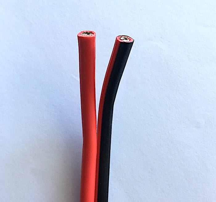
Use paired cable (positive and negative cables moulded together). It’s neater and easier to run than individual cables.
Where Do You Install Fuses?
This is super-important but often overlooked. If you want to eliminate the possibility of your pride and joy burning to the ground, read on.
Many DIYers forget why fuses are used in cable runs. We know we need to install a fuse, but often don’t think why. Let me give you an example.
Imagine you’re installing your second battery system on your dual cab ute. You want to power a fridge, a few Anderson plug outlets and some lighting in your canopy. So you need to run a supply cable from the starting battery back to the second battery system in the tray.
Where do you install the fuse for this cable? As close to the power source as possible, ie at the positive terminal of the starting battery.
Why? Assuming you’ve sized everything correctly, then the fuse only has one function. Its job is to protect the cable.
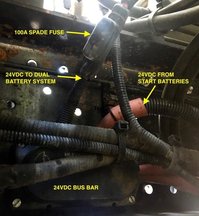
Let’s say you install the fuse at the wrong end, on your shiny new dual battery backplate in your canopy. What happens if the cable rubs through and shorts out onto the vehicle’s frame? Your poor cable will be carrying full current from the starting battery directly to the short. Pretty soon it will melt and most likely the insulation will catch fire. This is how many 4X4 fires start.
The same goes for any fuse. Always install it as close to the power source as you can.
Next time: Installing the dual battery system.
My Generator has a wide range of REDARC gear, including the Manager30.

Get your Traveller’s Guides
… and a whole lot more at our FREE RESOURCES Page!
Any questions or comments? Go to the Comments below or join us on Pinterest, Facebook or YouTube.
Any errors or omissions are mine alone.
NOTE: Redarc send us products to review from time to time. (That said, we purchased all Redarc products mentioned in this article.)
Go here for more How-To Guides and tips.
